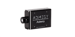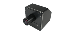
Lighting
LED
and Solid state lighting [SSL] is often referred to as the light of the
future: combining low energy consumption, efficient technology and long
product life times. An inherent challenge to the production process of
LEDs and Solid State Lighting products are driver related variations in
their optical characteristics such as brightness, color and flicker,
even in the same production batches. In order to assure a high-end
lighting product, it is necessary to measure these optical
characteristics during the development of LEDs and perform a 100%
inspection during the production processes. Typical LED – SSL
measurements include:
Geometry & optical configurations
| Radiometric | Spectroradiometric | Photometric | |
|---|---|---|---|
| Integrating sphere | Radiant power [W] | Spectral radiant power [W/nm] | Luminous power [lm] |
| Cosine corrector* | Irradiance [W/m²] | Spectral irradiance [W/m²/nm] | Illuminance [lm/m² = lux] |
| Cosine corrector* | Radiant intensity [W/sr] | Spectral radiant intensity [W/sr/nm] | Luminous intensity [lm/sr = cd] |
| Lens | Radiance [W/m²/sr] | Spectral radiance [W/m²/sr/nm] | Luminance [lm/m²/sr/ = cd/m² = nit] |
*Instead of cosine correctors, integrating spheres can also be used to determine [spectral] irradiance and radiant intensity / illuminance and luminous intensity. Flicker measurements can be carried out in combination with any of the optical configurations mentioned in the table above.
- Spectral power distribution to determine a light source’s total emitted power for each individual wavelength revealing information like for example color, CRI, CCT and many more.
- Radiance, irradiance & radiant intensity measurements to measure the amount of radiant power in W/m²/sr, W/m² and W/sr and parameters such as PAR.
- Luminance, illuminance & luminous intensity measurements to determine the light output in candela per square meter, lux and candela respectively.
- Flicker measurements to determine and adjust for flickering of light sources. Currently supported: flicker %, index and IEEE 1789 recommendation.
- 2D luminous surfaces measurements determine aspects such as uniformity of large luminous panels or surfaces.
How are you measuring?
With fibers and other accessories even more type of measurements are possible. Often used accessories are integrating spheres, cuvettes for fluids, light sources or filter holders.
A cosine corrector collects the light from the half space under 180 degrees. A typical application is the illuminance measurement of a lighting situation.
Consumers are used to enjoy top-quality displays in their mobile phones, tablets, laptops and even cars. Emerging technologies such as lighting surfaces for office and home illumination are expected to look equally perfect. Both displays and luminous surfaces are the main application areas for imaging colorimeters.
Measuring the luminance or color values at a specific location of the device under test is a typical use case when measuring displays. It can, however, also be meaningful to assess reflected light.
PCM2X-271

0.000 025 - 30 000 cd/m²
PCM2X-270
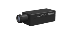
0.000 05 - 60 000 cd/m²
PCM2X-102

0.000 05 - 60 000 cd/m²
PCM2-100
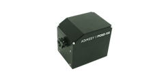
0.0003 - 15 000 cd/m²
Viewfinder Spectrometer

Standard lens 1.2° spot ⌀ 4.56 mm ‑ 6.71 m
Viewfinder Spectrometer

Close up lens 0.75° spot ⌀ 0.96 ‑ 1.47 mm
Colorimeter 2.1 mm
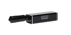
0.001 - 30 000 cd/m²
Colorimeter 5 mm

0.001 - 30 000 cd/m²
Colorimeter 10 mm

0.001 - 30 000 cd/m²
Colorimeter 10 mm wide-angle

0.000 3 - 7 500 cd/m²
Colorimeter 20 mm

0.0003 - 7 500 cd/m²
Colorimeter 27 mm wide-angle

0.0001 - 2 800 cd/m²
Spectrometer
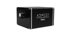
VIS 380 - 780 nm
High-End Spectrometer

VIS 360 - 940 nm


